2839195
| Question | Answer |
| External Loads | A body is subjected to only 2 types of external loads. Surface forces and body forces. |
| Surface forces | When two surfaces touch one another. Force evenly distributed and if area thin can be approximated by a linear distributed load. |
| Body Forces | When one body exerts a force on another without them touching i.e. gravity. Normally represented by a single concentrated force. i.e center of gravity |
| Support reactions | Only in the joints where restriction of movement occurs |
| Equilibrium | sum of forces and moments must equal 0 Draw a FBD |
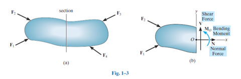
| Normal force, bending moment, shear force, torsional moment | |
| Coplanar loadings | Only have shear force, bending moment and normal force |
| Stress assumptions | Material is continuous Material is cohesive (no cracks) |
| Stress unit | Pa= 1N/m^2 |
| State of stress | A cubic section can be cut out of a member to give the state of stress shown below. |
| Stress directions | Normal stress acts normal to the change in area Shear force acts tangential to the change in area |
| Prismatic | All cross sectionals are the same |
| Homogeneous | same physical and mechanical properties all the way through |
| Isotropic | Same properties in all directions |
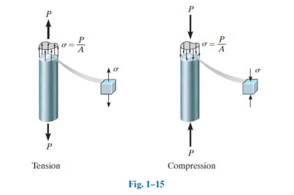
| Constant normal stress distribuion | uniform stress distribution means there must be a constant normal stress distribution. |
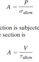
| Average normal stress equation | |
| Tension vs compression | Note that stress is in equilibrium. |
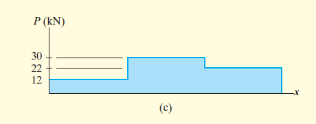
| Maximum average normal stress | Must analysis all sections where the cross sectional area or force changes for the largest P/A ratio. Use a axial/normal force force diagram. |
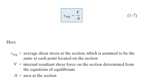
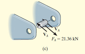
| Average shear stress equation | |
| Shear stress equilibrium | Shear stress mus be in equilibrium for pure shear to occur |
| Average shear special case | In some case double shear may occur in which case the shear force v is divided by 2 |
| Allowable stress equation | Same equation can be used but instead of force normal stress or shear stress can be used. |
| Finding allowable stress | |
| Deformation | When a body changes in size or shape |
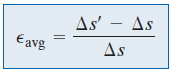
| Normal Strain | The change in length of a line per unit length |
| Normal Strain equation | |
| Shear Strain | Change in angle caused by deformation |
| Shear strain equation | |
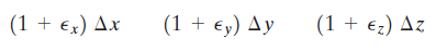
| Cartesian Normal strain | Equations represent the final lengths of the shape in the x,y and z co-ordinates |
| Cartesian Shear Strain | The equations for the approximate angles between sides |
| Cartesian strain summary | |
| Small strain analysis | IF normal strains <<1 |
| Strain changing by a function of x | integrate the Cartesian normal strain over the length of the bar. |
| Strain tip | USE TRIG! |
| Nominal/engineering stress | |
| nominal/engineering strain | |
| Stress/strain diagram | |
| Elastic behavior | Ranges up to the elastic limit. Up until this point the specimen returns to it's original shape once the load is removed. |
| Yielding | Occurs after the yield stress. Permanent deformation occurs here. Specimen continues to elongate even without an increase in load. |
| Strain Hardening | Occurs after yielding. Marks a point where more load can be handled by the specimen . This process will flatten off until in reaches the ultimate stress. |
| Necking | |
| Ductile material | Can be subjected to large strains before fracuring |
| Percent elongation formula | |
| Percent reduction in area formula | |
| Brittle materials | Materials that have little to no yielding before failure. |
| Hooke's Law | Equation represents the initial straight line of the stress strain curve |
| Elastic recovery | Once a specimen has been deformed it can recover after unloading this represents a slope E on the stress strain diagram. |
| Strain energy | Internal energy in a specimen when deformed by an external load |
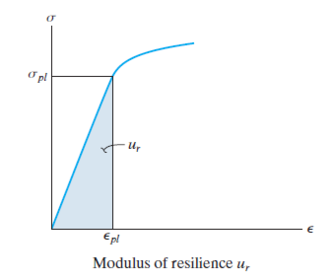
| Modulus of Resilience | Strain energy density when the stress reaches the proportional limit. i.e. area under the elastic region in a stress strain diagram. |
| Modulus of resilience equation | |
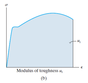
| Modulus of toughness | Area under the entire stress strain diagram. i.e. maximum amount of energy a material can absorb. |
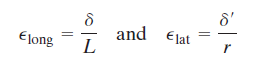
| longitudinal and lateral strain | Used to calculate Poisson's ratio |
| Poisson's Ratio | Usually negative and different for every material |
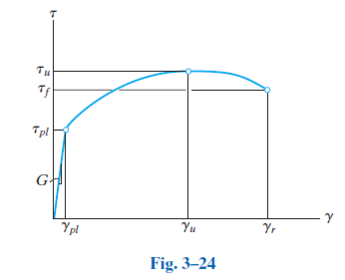
| Shear modulus of elasticity | Represents the slope of a t-y diagram |
| The shear stress strain diagram | |
| Shear modulus/modulus of elasticity formula | |
| Another strain defiition | Can be thought ofas change in length over change in time. Therfore can intergrate to find the length |
| Saint-Venant’s principle | Where after appoint the localised stress becomes the same as the average stress |
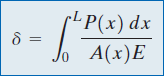
| Displacement in terms of x | |
| Displacement for constant force, E and area | |
| Displacement for segmented forces, areas or E's | |
| Displacement sign convention | |
| Principle of superposition | When the stress or displacement of segments can be added together to compute the overall stress/dislacement for the member. |
| Condition for superposition | 1. Load must be liearly related to the stress of displacement 2. Load must not significantly change the geometry or configuration of the member. |
| Compatibility condition | equation that specifies conditions for displacement |
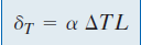
| Thermal displacement equation | |
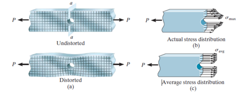
| Stress concentrations | Complex stress distribuions can occur where the cross sectional area in a member changes. |
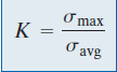
| Stress contcentraion factor equation | |
| Stress concentration graphs | Graphs can help to determine the stress concentration factor for many specimens |
| Torque | Torque is a moment that twists a member around it's longatudinal axis |
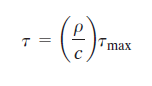
| Torision: Shear stress vs max shear stress equation | P is the radial position C is the outer radius |
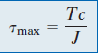
| Torision: Max shear stress equation | T is the internal torque c is the ouer radius J is the polar moment |
| Torsion: Shear stress equation | |
| Polar moment: Solid shaft | |
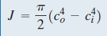
| Polar Moment: Tubular shaft | |
| Power transmission | The works per unit time required to rotate the shaft |
| Power transmission equation | |
| Power Transmission Frequency formula | This formula can be used or P=Tw Where w is the angular frequency |
| Shaft design formula | Used to design the geometry of the specimen i.e. using J or c |
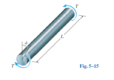
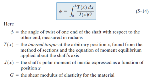
| Angle of twist | The amount of rotation or twist that occurs in a secimen |
| Angle of twist in terms of x | |
| Angle of twist for a consant cross section | |
| Angle of twist for multiple torques | |
| Sign convention Angle of twist | Use the right hand rule |
| Note on summing angles of twist | Only valid if shear stress does not exceed the proportional limit. |
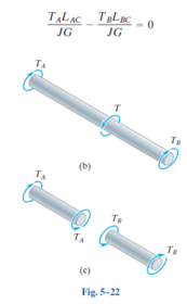
| Torsion case: Two fixedsupports at either end of a member | angle of twist must equal 0 |
| Angle of twist case 2: two materials bound together | Angles of twist must be equal to each other |
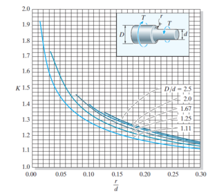
| Torsion: Stress concentrations | The torsion formula can not be used when there is a sudden change in cross secional area. So K is used in this formula |
| Torsion: Stress concentration graphs | Stress concentraton graphs can be used to calculate K |
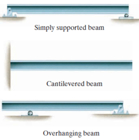
| Example of different beam types | |
| Shear and moment diagrams | The shear force and bending moments graphed across a position x along a beam |
| Beam sign convention | |
| Beam | Long straight member loaded perpendicular to it's longatudinal axis |
| Complex loadings for determining V and M | Relationships between the diagrams can be used todetermine the graphs shape. |
| More relationships | |
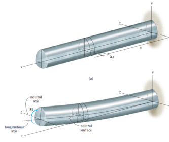
| Bending a straight member: assumption 1 | The longatudinal axis does not experience any change in length |
| Bending straight member: assumption 2 | All cross sections remain plane and perpendicular to the longaudinal axis |
| Bending a straight member: assumption 3 | And deformation in a cross sections plane will be ignored |
| Label of axis (straight member) | |
| Strain for a deformed straight member | |
| Define p and y variables | |
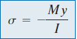
| Relating stress to the maximum stress equation | Y is the distance from the y axis c is the radius |
| Flexure formula: Maximum stress | Where c is the radius |
| Flexure formula: At a point | |
| Flexure formula condition | Resultant internal moment is equal to moment produced by the stress distribuion about the normal axis. |
| Normal Stress at a point | |
| Angle of moment at a single point | a is the angle of the neutral axis theta is the angle of the moment |
| Stress concentrations: when you can't use the flexure formula |
Want to create your own Flashcards for free with GoConqr? Learn more.